1. Auxiliary views
1.1 Study of auxiliary planes | 1.2 Projection of objects on auxiliary planes | 1.3 Completing the regular views with the help of given auxiliary views
Sectional Views
1.4 Types of sections | 1.5 Conversion of pictorial view into sectional orthographic views
2. Conversion of Projections
2.1 Introduction to Orthographic & Isometric projections. | 2.2 Conversion of isometric view into Orthographic Views (Simple Machine Parts) | 2.3 Draw missing view from the given Ortho graphic views-simple components | 2.4 Conversion of orthographic views into isometric Views (Simple Machine Parts)
3. Rivet and Riveted Joints
3.1 Introduction and classification of Fasteners | 3.2 Shape of Rivet heads | 3.3 Types of Riveted joints
4. Conventional Representation
4.1. Standard convention using SP–46(1988)
(a) Materials C.I. , M.S, Brass, Bronze, Aluminum, wood, Glass, Concrete and Rubber , (b) Long and short break in pipe, rod and shaft. , (c) Ball and Roller bearing, pipe joints, cocks, valves, internal/External threads. , (d) Various sections- Half, removed, revolved, off set, partial and aligned sections. , (e) Knurling, serrated shafts, splined shafts, and chain wheels. , (f) Springs with square and flat ends, Gears, sprocket wheel (g) Countersunk & counter bore., (h) Tapers (i) Conventional Representation of holes, bolts, nuts and rivets.
5. Limits, Fits and Tolerances
5.1 Characteristics of surface roughness – Indication of machining symbol showing direction of lay, roughness grades, machining allowances , manufacturing methods | 5.2 Introduction to ISO system of tolerance, dimensional tolerances, and elements of Interchangeable system, hole &shaft based system, limits, fits & allowances. Selection of fit. | 5.3 Geometrical tolerances, tolerances of form and position and its geometric representation.
6. Details to Assembly
6.1 Introduction | 6.2 Bearing–Foot Step Bearing & Pedestal Bearing | 6.3 Lathe tool Post | 6.4 Keys, Knuckle Joint and Cotter Joint | 6.5 Screw Jack | 6.6 Steam Stop Valve | 6.7 Pipe Joints (Union Joint, Expansion Joint & Spigot & Socket Joint)
7. Assembly to Details
7.1 Introduction | 7.2 Pedestal Bearing | 7.3 Lathe Tail Stock | 7.4 Drilling Jig | 7.5 Automotive parts (Piston & Connecting rod) | 7.6 Couplings–Flange Couplings, Flexible Couplings Universal couplings & Oldham’s Coupling | 7.7 Fast & loose pull | 7.8 Valve–Not more than eight parts
| About the Book :
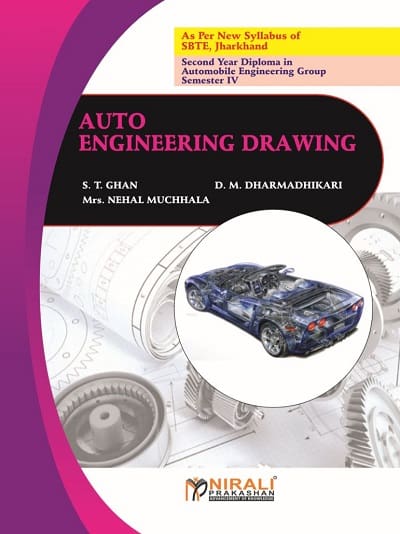
It is indeed a great pleasure and proud privilege for the authors to present this book on the subject “Auto Engineering Drawing” for Second Year Diploma in Automobile Engineering for Semester – IV.
This book is strictly written according to New Revised Syllabus of S.B.T.E., Jharkhand. In this book, the complete subject is explained in a lucid manner. Lots of solved examples with procedure and figures, and all variety of questions are included. |


 Zoom
Zoom



Reviews
There are no reviews yet.