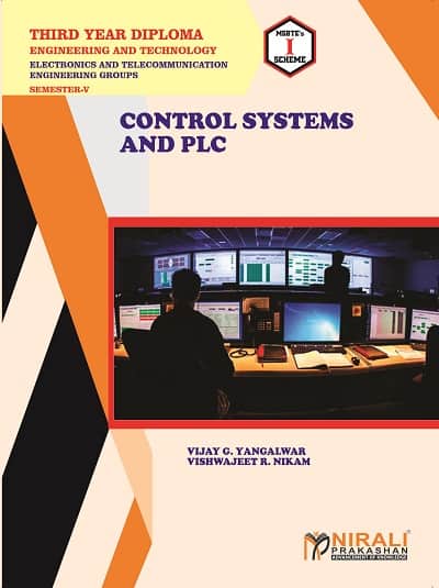
- Basics of Control System (Hrs. 10; Marks 12)
1.1 Control Systems : Basics of Control System, Block Diagram and Practical Examples
1.2 Classification of Control Systems : Open loop and Closed loop Systems – Block Diagram, Practical Example and Comparison, Linear and Non-linear Systems, Time Varying and Time Invarying Systems – Practical Example and Comparison. Servo System
1.3 Transfer Function : Closed loop and Open loop System – RC, LC and RLC Circuits – Differential Equations and Transfer Functions and Analysis using Laplace Transform
1.4 Block Diagram Reduction Technique : Need, Reduction Rules
- Time Domain Stability Analysis (Hrs. 16; Marks 16)
2.1 Time Response : Transient and Steady State Response
2.2 Standard Test Inputs : Step, Ramp, Parabolic Impulse and their corresponding Laplace Transform
2.3 Analysis of First and Second Order Control System :
(i) Poles and Zeros : s-plane Representation, Order of System (0, 1, 2) – Standard Equations, Examples and Numerical Problems
(ii) First Order System : Analysis for Unit Step Input, Concept of Time Constant
(iii) Second Order System : Analysis for Unit Step Input (No Derivation), Concept, Definition and Effect of Damping
(iv) Time Response Specifications (No Derivations) : tp, ts, tr, td, mp, ess, Numerical Problems
2.4 Steady State Analysis : Type 0, 1, 2 Systems-Steady State Error and Error Constants, Numerical Problems
2.5 Stability : Concept of Stability, Root Locations in s-plane and Analysis – Stable System, Unstable System, Critically Stable Systems, Conditionally Stable System, Relative Stability
2.6 Routh’s Stability Criterion : Steps and Procedures to find Stability to Routh’s Stability Criteria
- Process Controllers (Hrs. 08; Marks 10)
3.1 Process Control System : Block Diagram, Functions of Each Block
3.2 Control Actions :
(i) Discontinuous Mode : ON-OFF Controllers – Equation, Neutral Zone
(ii) Continuous Modes : Proportional Controller – Offset, Proportional Band, Proportional, Integral and Derivative Controllers – Output Equation, Response, Characteristics
3.3 Composite Controllers : PI, PD, PID Controllers – Output Equation, Response
- Fundamentals of PLC (Hrs. 12; Marks 14)
4.1 PLC – Block Diagram, Classification (Fixed and Modular PLCs), Need and Benefits of PLC in Automation
4.2 Description of Different Parts of PLC : CPU – Function, Scanning Cycle, Speed of Execution, Power Supply – Block Diagram and Function of Each Block.
Memory – Function and Organization of ROM and RAM. Input and Output Modules – Function, Different Input and Output Devices of PLC (only names and their uses)
4.3 PLC Installation
- PLC Hardware and Programming (Hrs. 18; Marks 18)
5.1 Discrete Input Modules : Block Diagram, Specifications of AC Input Modules and DC Input Module. Sinking and Sourcing Concept in DC Input Modules
5.2 Discrete Output Modules : Block Diagram, Description and Specifications of AC Output Module and DC Output Modules
5.3 Analog Input and Output Modules : Block Diagram, Specifications
5.4 Input/Output Addressing of PLC : Addressing Data Files, Format of Logical Address, Different Addressing Types
5.5 PLC Instruction Set : Relay Instructions, Timer and Counter Instructions, Data Movement Instructions, Logical and Comparison Instructions
5.6 PLC Programs Using Ladder Programming Language


 Zoom
Zoom



Reviews
There are no reviews yet.